Large-capacity Filters FGC 140 to 4 000
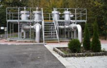
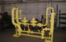
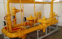
This gas dust filter is designed for separating mechanical impurities of the gaseous substance: air, natural gas, propane-butane and other non-aggressive gases in compliance with valid legislation.
Equipment description
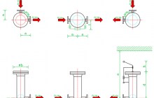
- Inlet and outlet branches PN 16 to PN 40 (standard version) for gas inlet and outlet, located at the bottom of the equipment according to the customer’s specifications – left, right, straight
- Drain outlet (connected at the bottom, for draining impurities and condensates), usually ends with a DN 25 blind flange (DN 50 for FGC 4000), however, it can also be delivered with a flange, welded, or threaded ball closure with a lid on request
- Top filter lid (formed by a neck flange connected by screws through sealing with a blind flange, or a quick-closing valve)
- Replacement filter cartridge (located inside the equipment, either cellulose, or special fabric)
The filter may be equipped with a device for measuring pressure loss on the filter cartridge. Lugs are welded onto both branches, to which stoppers are attached. The stopper outlets are connected to the distribution block by pipes. The top outlet of the distribution block is connected to an indicative or differential manometer.
The manometer type depends on the customer. We are able to deliver differential manometers with an output for remote data transfer. The filter is equipped with sockets for attachment to the frame.
We also manufacture filters of up to PN 250 on request.
High pressure filters – Technicla parameters
Middle pressure filters – Technical Parameters
GC-EP02 Electric Preheater
The electric gas preheater is designed for preheating natural gas in the gas regulation stations. It can also be used for preheating air.
This type can be delivered with several modifications (according to DN, PN and heating output).
The electric heating control device is installed on the side of the preheater body and it includes a thermostat and a thermal fuse. The thermostat is used as the first reciprocating level of temperature protection and the switch is set to the temperature of 30 °C. The thermal fuse is used as the second irreversible temperature protection and it is set to 70 °C.
The fully automated gas heating control is executed by electronic switching of the feeding circuit. The switching frequency is controlled by an external electronic regulator. The temperature sensor is located behind the preheater (regulation station output). The output temperature is maintained by electronic regulation with accuracy of 1 °C.
| TYPE | PN (bar) | DN (mm) | P (kW) | U (V) |
|---|---|---|---|---|
| GC-EP02 | 40/63 | 25/32 | 2 | 230 |
| GC-EP02 | 40/63 | 25/32 | 1 | 230 |
Files
Questions?
Do you want to ask us something? Write us. Our specialist will respond to your inquiry within 1 week.


